Worse sensitive. 1stis machine is composed of an enamel wire coil filter but 2nd machine is composed of PCB pattern coil one. I added the resistor for impedance matching so this causes much loss.
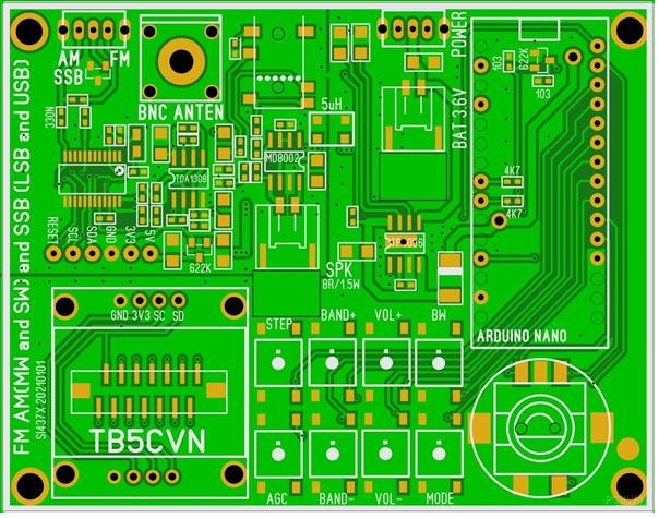
I bought the Si4732 receiver kit and assembled it. This is the same as ATS-20 with the case. The original PCB is based on Turkish HAM, TB5CVN copied and is selling it on PCB WAYs as USD5.
Connecting Si4732 receiver with airband receiver IF
There is 10.7MHz IF output on the Chinese remodeled receiver. Si4732 is set 10.7MHz AM and fed the above signal. I could hear airband radio communication on this combination. It is special as DSP receiving feeling. When signal comes, once calm and after then the demodulated sound is coming up.
For the sake of sketch improvement I had changed Arduino nano to be connected on PCB. So female header on PCB and soldered male header on Arduino nano. So I removed nano from PCB. Then I found that they had soldered Vcc, GND, and internal Vcc supply node of USB-Di cathode of nano board. To prevent USB +5V supply they remove the diode and they connected +3.3 line to Di cathode node by tricky style.
I would not use a battery and I shall supply Vcc from USB to nano. So I soldered 1S1588 of a silicon diode. It reduces 0.8V and supplies voltage results 4.2V This works well.
I had soldered and turned on. Then the circuit is unstable still. There occurred stacked along with i2c interfacing. I checked the circuit diagram and I could not find AL capacitors on a power line. I observed DC line by oscilloscope and found some hundred mv of ripple on it. I added 47uF AL capacitors on the line.
I had consumed much time to resolve this setting. 1S1588(same as 1N4001) is working well. Arrived Arduino sketch was 1.1.5 as a very old version. I shall instead it to current versio as V3.x.x.
PU2CLR Mr.Recardo is a very generous person to admit Chinese clone suppliers being using his library without any notice. He is providing version-up information for Chinese kit purchasers. I will introduce it with a Japanese translation.
To study to make up the airband receiver of Si4732 I bought a Chinese Si4732 all band receiver kit. I had completed the Chinese receiver kit optionally with digitalized LO. Si5351a + analog receiver is fine. Next step to divert this LO I could combine Si4732 with it converting the frequency of 120MHz band to 10.7MHz IF on Si4732. --- Unfortunately, I had stacked not to operate this SDR radio.
Naturally, these Chinese kits had not been used to accompany every assembling information and I guessed that a similar receiver installed in the case is the same source. I shall find assembling instructions and circuit diagrams. There are selling assembled PCB, only PCB, and set installed in the case. It may be the same design.
因みにPCB WAYでUSD5で売られている基板はトルコのハムがパターン設計したらしい。
BTW PCB WAY is selling PCB designed by Turkish HAM which is de fact standard of these kits.
I looked at the set installed in the case and found panel PCB of LCD, Switches, and rotary switch is optional on PCB for a panel. The PCBs are connecting with each other via a ribbon cable.
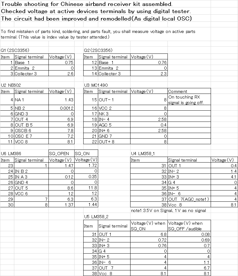
The pop sound is coming out when the squelch is on/off. AGC voltage and squelch volume tuning voltage are compared by LM358 and the circuit is muting RX sound signal at LM386 input nevertheless LM386 is active. Then a signal is faded but Pop noize is generated.
This idea was coming from Mr.Chiba of ITEC electric LAB. He had introduced this idea in CQ ham radio magazine in Nov 1992. For the shake of squelch going, it lets LM386 eliminate amplitude by a de-biassing amplifier. This forces LM386 output signal to be fully choked.
Recently I found R29 being 1k well depending on LM386 lot. Formerly I used 47k. If you confront squelch malfunction, please check this value.
何か対策ないかと思っていたら、1992年CQ HAM RADIO別冊トランシーバー製作入門にアイテック電子の千葉さんのアイデアが記載されていました。信号をON/OFFするのではなく、スケルチ信号でLM386の増幅機能を止めようというものです。スケルチ信号でアンプ動作を止めようというものです。この方式では信号時(受信信号なしAGCがL)には出力がなくなり、音が出ません。
I'm trying to install a digital local oscillator within the original Chinese airband receiver kit. Accordingly, I shall make up a compact local oscillator circuit with a tiny graphic LCD and Arduino Pro Mini board. To reduce function keys I made the newer sketch by using a Rotary encoder and its push switch operation approaching. Such combination leads to below circuit diagram.
To utilize the rotary encoder's push switch I adopted a double crick operation. Operation methods are below:
1. When the push switch is on, the machine's going into FUNCTION selection mode by the rotary encoder. The display of function code is blincking displayed by heartbeat timing('#13 LED on/off).
2. Then the rotary encoder's push switch is on, the function is determined temporarily decided.
FUNCTIONs are "Frequency increasing & decreasing", "STEP frequency increasing & decreasing", "Reading out the frequency of the selected memory channel", and "Writing the frequency on the selected memory channel".
3. Then the rotary encoder's push switch is double click on ( 2 times during 500mS), memory write is performed. Specially SCAN mode it changes into AUTOMATIC SCAN mode.
Therefore I come to study new combination of receiver kit, Si5351a local oscillator, and Si4735-D60. There are several issues how to configure RF section, how to display, how to operate with swiches, and how to install tiose into case.