nobcha23のエアバンド受信機自作ブログ DIY airband receiver BLOG

エアバンドレシーバーキットの組み立て、改造を手掛けます Assemble and remodel Chinese airband receiver kit

I posted my DIY R909-DSP video on YOUTUBE YOUTUBEに紹介ビデオアップロードしました

Arduino制御でSi4732+Si5351a+TA2003+OLED表示のエアバンド/FM受信機のスケッチデバッグが大体終わったので、紹介ビデオを作りました。
www.youtube.com

www.youtube.com

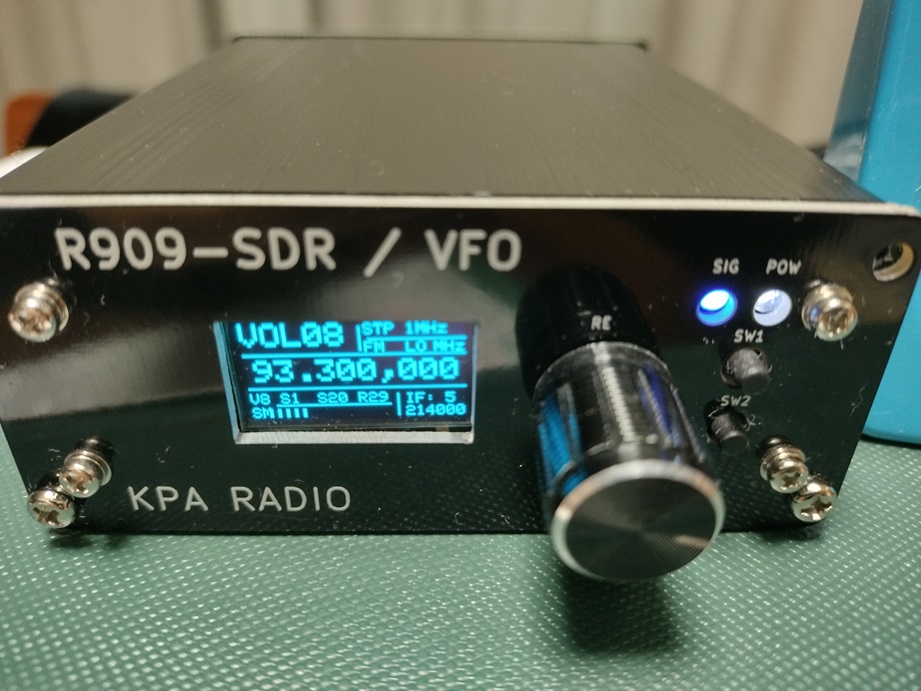
アルミ引き抜き材のケースに入れ、フロントパネルとバックパネルも基板で作成し、ATS20みたいな感じにまとめました。

内蔵基板はデジタル制御部のPANEL基板と、受信機関連のRF基板からなっています。

感度がいまいち(-85dBm)だったので、LNAを前置しています。対策としてLNA追加のRF基板を設計・改版したいと思います。


As I finished to debug for Arduino based Si4732+Si5351a+OLED airband radio, I edited the introduction video. I had designed this radio from scratch.

I installed the radio electronics into the aluminum mold case as looking like as ATS20.

There are PANEL PCB and RF PCB. The sensitivity is not enough (-85dBm) and I added LNA module on radio. So I would like to reedit the RF PCB pattern.

www.hackster.io


ケースのパネルを基板で To make the case panel by PCB

J909-DSPのケースですが、Aliexpressで売ってるアルミ引き抜き材のケースとフロント、バックのパネルはプリント基板で作ってみました。


PCB


出来上がりはATS-20みたいになりました。
The assembled example is here. It looks like as a ATS-20.

CASE


またまたPCBGOGOに依頼。事前チェックで引っ掛かり、基板を作る前に相談して解決。

PCBGOGOリンクURL:https://www.pcbgogo.jp/promo/nobcha23


I found the case made of the aluminum moldng material at Aliexpress.
As drilling the case is hard, I made the front and back panel by PCB.


Many thanks for advising prior to produce the PCB. This time I got some advices from PCBGOGO stuff.


Front

Back


なおスケッチの方はまだデバッグ中。AB受信もFM受信もチャンネルメモリーもうまくいったが、AB/FM切り替えにバグあり対策中。
I'm still debugging for J909-DSP sketch.

www.youtube.com


R909-DSP-OLED版の操作フロー The flow diagram for R909-DSP-OLED version

Si4732を親受信機に、TA2003フロントエンドにSi5351aモジュールを局発として付加したエアバンド受信機を試作しています。OLED表示の構成にしたものではブロックダイヤグラムは次の通りです。


I’m making the airband receiver with TA2003 as a frond end, Si5351a as a local oscillator, and Si4732 as a mother receiver. The block diagram of OLED display type is below.


ブロックダイヤグラム


その操作体系ですが、1.ロータリーエンコーダー・スイッチを使い、ルーレット方式でメニューを入れ替え、2.プッシュスイッチで機能を選択決定、3.ダブルプッシュで関連パラメーターをEEPROM書込みするというスタイルです。


This rig's operation flow is the following steps. The rotary encoder is showing menu as a roulette and to select a cirtain one on RE-SW pushing. Double pushing is effecting to store the related parametrs in EEROM. l will introduce it by key operation flow diagram as below. 


操作フロー

Operation flow

さて、スケッチですが、当初ADAFRUITSのOLED、ETHERKITの5351a、PU2CLRの4732ライブラリーを組み込むとフラッシュ使用量が100%を越えました。試しに5351aをTJ labのコードにしたら、90%を下回ることができ、他にもメモリー削減努力したら83%まで低減できました。SRAMも1kは残さないといけないので、F(***)なども多用し50%以下となっています。


At first the usage of flash(ADAFRUITS'sOLED、ETHERKIT's5351a、and PU2CLR's4732 are contained.) was more than 100%. And I changed ETHERKIT's5351a to TJ lab's code, then it became less than 90%. Also the other effort resulted 83% usage. To save 1k byte SRAM for OLED lines buffer I used F(***) function and it was less than 50%.


OLED‗Format


Front panel


ビデオは次です。

There is a video but the version is last but one.

www.youtube.com


RBA-03と言うDIYキット There is an air band radio DIY kit of RBA-03

マルタ島ハムから教えてもらったのですが、BRA-03と言う航空無線機基板キットがあるようです。
I was introduced an air band radio DIY kit of RBA-03.

早速ググってみるとYOUTUBEに紹介ビデオがあり、基板などの資料、さらにPCBWAYでガーバーファイルのダウンロードサービスが行われています。

By Googling I found the introducing video on YOUTUBE and also they are delivering the bare PCB at PCBWAY WEB.

RBA-03, Aviation Airband Receiver on Test Platform, 110-138MHz AM, Sibiu Airport Beacon data


RBA-03 AIR BAND RECEIVER

回路はシングルスーパーでTA7358A自励発振+ディスクリートIFです。ちょっと感度が低いかも・・。ちょうど、Si4732受信機試作過程でSi5351a利用局発信号発生基板を作り、スケッチ書いたところなので、これを組み合わせるのも面白そうと思っています。

It is a single super heterodyne by using TA7357A self oscillator. The IF is configured with the descrete transisters. I could divert the current receiver's loacl clock portion for remodelling this radio.


The below photoes are the current debugging receiver.


R909-DSP-1602機の操作フロー Operation flow of R909-DSP-1602 radio

Si4732を親受信機に、TA2003フロントエンドにSi5351aモジュールを局発として付加したエアバンド受信機を設計試作しています。ブロックダイヤグラムは次の通りです。 I’m designing the airband receiver with TA2003 as a frond end, Si5351a as a local oscillator, and Si4732 as a mother receiver. The block diagram is below.

Block diagram

ブロックダイヤグラム


その操作体系ですが、中国製エアバンドレシーバーキットのデジタルLO改造(二号機)から始まり、R909とそしてR909-SDR-1602機では操作の流れは同じです。ロータリーエンコーダースイッチを使い、ロータリーエンコーダーを回転させルーレット方式でメニューを選び、ロータリーエンコーダープッシュスイッチで機能を決定するというスタイルです。フロー図を描いてみました。
This rig's operation flow is following R909 style. The rotary encoder with the push switch is acting the roulette to round memu and to select on pushing. I will introduce it by key operation flow diagram as below. 

Operation flow

youtu.be


今後追加組み込みの機能で予定されているのは、Si5351aの基本周波数誤差設定とか、Si4732利用受信機では受信帯域選択などです。 Later I would like to add error correction for Si5351a and selection signal band width.


www.youtube.com


R909-DSP感度アップ模索 To improve the sensitivity for R909-DSP

TA2003+Si5351a+Si4732+Arduinoエアバンド受信機のデバッグ中です。tinySAultraのRF信号発生機能を利用して調べたのは報告しました。 I checked the sensitivity of TA2003+Si5351a+Si4732+Arduino RX by using tinySA ultra RF generator function.

今回のR909-SDRはHRD-737(ANT端子をSMA改造したもの)と同格、ちょっと使い物にならないレベルでした。 Concerning with a former result this R909-SDR RX is same level as aHRD-737(ANT node remodelled for SMA connector). 

比較表


何とかしないといけないと、考え巡らせ、回路見直し、TA2003参考回路と違うのはFM_RF_OUTの負荷であることに気が付きました。1kΩだったのをコイルに変えました。120MHzで1kΩぐらいのインピーダンスと言うことで400nHにしました。手持ちのアミドンT25-2に8t巻いてnanoVNAで50Ω直列治具で測ったら90Ω+365nHでした。
To increase sennsitivity, I reviewed the schematics and found the the load of TA2003's FM_RF_OUT being insufficient. To replace 1 kohm resister. I made 400nH coil by T25-3 8 turns. By measuring with nano VNA and 50 ohm jig, it reports 90 ohm + 365nH. 

nobcha23.hatenablog.com


抵抗からコイルに入れ替え測ると、受信感度(聴感)が-83.5dBと改善されました。しかし、まだ足りないです。そこで30dBLNAを入れてみました。-117dBmとなりました。この基板を改版するときはLNAを追加するようにします。 When I changed 1 k resister to 400nH coil, the sensitivity comes up to -83.5dB comparing with former -70dBm. Still low and I add the Chinese 30dB LNA, so it comes -116dBm.

Radios and tinySA RF generator

現在のところ、感度、聴感でこのR909-SDR-1602+30dB-LNAが手持ち受信機の中でトップになりました。まだ、いくつか改良点があるので、しばらく楽しめます。


ところで、この実験中に気が付きましたが、tinySAultraのRF信号発生機能は表示は-126dBmまで絞れるのですが、-115dBmより下げても聴感にあまり変化ありません。 BTW, tinySAultra's RF generator could generates down to -126dBm, but I felt that there is scarcely diference under -115dBm.

-----------------------------------------

SPEC調べたら、-115dBmより下げても変化ないのはその通りでした。

シグナルジェネレータ
         tinySA ULTRA
周波数      100kHz~800MHz
波形       正弦波
出力レベル -110dBm~-20dBm
精度       ±2dB(-72dBm以下は精度低下)
変調       NFM、WFM    AM、FM

Si4732エアバンド受信機デバッグ中 

先の記事で紹介したようにATmega328Pのメモリー使用量を抑えることができ、OLED版の実験が進んでいます。
I’m debugging Arduino controling Si4732 radio for airband communication receiver.
I combined JCR's OLED display with PU2CLR libraly and Si5351a.