nobcha23のエアバンド受信機自作ブログ DIY airband receiver BLOG

エアバンドレシーバーキットの組み立て、改造を手掛けます Assemble and remodel Chinese airband receiver kit

エアバンドレシーバー組み立てトラブルシューティング 電圧チェックポイント  Trouble shooting after assembled by checking voltage

ーーーーーーーーーーーーーーーーーー
amazoneやeBAYなどで売っている航空 
無線用受信機キットを組み立て、改造   
しております。キットの組み立て、調整、
そして受信周波数表示から、さらに一歩
進んでデジタル型局発の試作と局発       
外部入力改造を行います。                     
ーーーーーーーーーーーーーーーーーー

中国製のエアバンドレシーバーキットを組み立てて、遊んでいます。


先のメールで紹介したWEBの中でも、結構な方が組み立てても動かないというクレーム?ヘルプメッセージをポストされています。


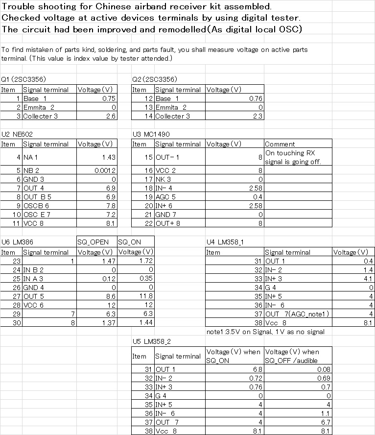
その中でトラブルシューティングのため主要ICのテスター電圧チェックのポストがありました。これは組み立てて動かないときの目安になりそうです。動いている基板の主要と言わず、ICとTRの電圧をテスターで測って表にまとめてみました。

 (実はデジタルテスターで測るというちょっと荒っぽいやり方は米国のBLOGで教えてもらいました。そしてそこの議論に参加しようとしたら、イタリアの人から全部のICの電圧を測ったのなら教えてよと言われ、このブログにしました。まあ、国際協力持ちつ持たれつです。)


f:id:nobcha23:20191118223140j:plain

テスターで電圧チェック

---------------------2021.09.21-----------------

修正版の各部電圧チェックリストを作りました。

f:id:nobcha23:20210612221934j:plain

修正版トラブルシューティング用電圧チェックリスト

------------------------------------------------
I'm attempting to assemble, and
remodel for Chinese receiver kit.
To improve performance I would
like to add frequency displaying
and digital attended local ocsillator
modified.
------------------------------------------------


I'm now assembling Chinese airband receiver kit and remodelling it.


As I introduced POST of "DIY Kit for Aircraft Band Monitoring", there are many person compliant with no working after assembled.


There was  a post which was handled IC terminal voltage check by tester. I thought that this was wll for trouble shooting. And I had measured every voltage of active parts as above list.


f:id:nobcha23:20191118223223j:plain

Check terminal voltage by digital tester


f:id:nobcha23:20190630142551j:plain

Circuit diagram


-ーーーーーーーーーーーーーーーーー2021.09.21-----------

I reedited the node voltage list as below to avoid issues.

f:id:nobcha23:20210612221934j:plain

The reedited list


rover.ebay.com

  Airband receiver aluminum case

エアバンドレシーバーキットのWEB情報

ーーーーーーーーーーーーーーーーーー
amazoneやeBAYなどで売っている航空
無線用受信機キットを組み立て、改造    
しております。キットの組み立て、調整、
そして受信周波数表示から、さらに一歩  
外部入力改造を行います。                         .
ーーーーーーーーーーーーーーーーーー

中国製造のエアバンドレシーバーキットを組み立てて、遊んでいます。


組み立て、周波数デジタル表示、局発周波数のデジタル制御発生、LNAの追加まで来ました。周波数をデジタル制御して安定になったので、次は受信帯域のナロー化と思ってましたが、その前にもう一枚キットを買ってしまいました。


初めに組み立てたのはエナメル線コイルの初段フィルタ、今度のはプリントパターンコイルです。


このフィルタの特性があまりよくありません。なので、改善の情報はないものかとWEB情報を探ってみました。


このキットの情報交換は次のところにあります。

DIY Kit for Aircraft Band Monitoring | The SWLing Post

さらにバリキャップ印加電圧をデジタル化する改造を見つけました。

ZL2PD Airband Receiver Controller


残念ながら、プリント基板フィルターの改善策の情報はみつかりません。


 ------------------------------------------------
I'm attempting to assemble, and
remodel for Chinese receiver kit.
To improve performance I would
like to add frequency displaying
and digital attended local ocsillator
modified.
------------------------------------------------

I'm now assembling Chinese airband receiver kit and remodelling it.


I just completed displaying apparatus of receiving frequency, degital generating local oscillator , adding LNA, and narrower intermideate frequency band.

Before to try to remodel narrower, I bought next kit.


This kit PCB is identified from former kit of coil type front end.


This style of front end filter is no good for filtering ability. I had serch for improvement of band pass filter.


After searching related information on internet, I found below posting.

DIY Kit for Aircraft Band Monitoring | The SWLing Post


Unfortunately I could not find filter improvement information yet.


rover.ebay.com

  Airband receiver aluminum case

プリント基板フィルター型基板のフロント部分通過特性 Pass band characteristics for PCB pattern filter

ーーーーーーーーーーーーーーーーーー
amazoneやeBAYなどで売っている航空 
無線用受信機キットを組み立て、改造    
しております。キットの組み立て、調整、
そして受信周波数表示から、さらに一歩   
進んでデジタル型局発の試作と局発        
外部入力改造を行います。                      
ーーーーーーーーーーーーーーーーーー

f:id:nobcha23:20191014140905j:plain

プリント基板パターンフィルタ

プリント基板フィルター型基板のフロント部分だけを組み立て通過特性を見てみました。GigaST4.0のTGモードで見てみます。


f:id:nobcha23:20191026201149j:plain

プリント基板パターンフィルタでの通過特性


エナメル線コイルのフィルターはこんなのでした。


f:id:nobcha23:20190518163249j:plain

エナメル線コイルのフィルター帯域

f:id:nobcha23:20190708194941j:plain

空芯コイル式のフィルタ特性

さて、どうしたものでしょうか。

 (可変コンデンサを利用して特性改善を図りました

 ------------------------------------------------
I'm attempting to assemble, and
remodel for Chinese receiver kit.
To improve performance I would
like to add frequency displaying
and digital attended local ocsillator
modified.
------------------------------------------------


 I shall improve pass band characteristics for print circuit coil type.


 I just assembled newly gotten PCB on front end portion and checked pass band characteristics by using hobby spectrum analyser of GigaSt4.0 as below. This is gotten by tracking generator mode.


 It was vary unstable characteristics.Refer to upper photo.


The former assembled filter was below. This was enamel wire coil style.

 (I just tried to tune front end band pass filter better by replacing capacitors from fixed to variable.)


---追記 Apend‐――-------------------------------------

関連書き込みも参考にしてください。  Please refer related post.


エアバンドレシーバーキットの組み立て、改造を手掛けます Assemble and remodel Chinese airband receiver kit

nobcha23.hatenadiary.com

nobcha23.hatenadiary.com

nobcha23.hatenadiary.com


If you are interested in purchasing this kit, please click below line.

エアバンドレシーバーキット

もう一セットキットを買いました I bought more one.

 ーーーーーーーーーーーーーーーーーー
amazoneやeBAYなどで売っている航空 
無線用受信機キットを組み立て、改造      
しております。キットの組み立て、調整、
そして受信周波数表示から、さらに一歩  
進んでデジタル型局発の試作と局発       
外部入力改造を行います。               
ーーーーーーーーーーーーーーーーーー

------------------------------------------------
I'm attempting to assemble, and
remodel for Chinese receiver kit.
To improve performance I would
like to add frequency displaying
and digital attended local ocsillator
modified.
------------------------------------------------


さて、中国産のエアバンドレシーバー回路部品キットを使って、もう少し改造なんぞをやってみたいと思います。なので、もう一セット分キットを買うことにしました。

I would like to remodel more by using Chinese airband receiver kit and I would buy more.


アマゾンに注文しておよそ一週間たつと、中国郵便でやってきました。

I put order for Amazone and parts kit arrived after one week via Chnese postal service.


今回のロットではフロントエンドの帯域フィルタが基板パターンコイルのものです。

This PCB is organized by print circuit pattern inducter filter.


f:id:nobcha23:20191012195102j:plain

キット付属の説明図のバージョン

f:id:nobcha23:20191014140905j:plain

フロントエンド部の帯域フィルタ部回路とPCBパターン

基板のシルクC3とC4が入違っているようです。

I found mistake of silk screen of C3 and C4 replaced.


次に組み立てて帯域特性を見ることにしますが、ちょっとお待ちください。

Next step I will assemble pass band filter section and check the characteristics of filter. Please wait.


電子工作ランキング https://ping.blogmura.com/xmlrpc/0ybopw0ua89q/


KKmoon レシーバーキット エアバンドラジオ レシーバー DIYキット 航空バンドレシーバー 高感度


rover.ebay.com

エアバンドレシーバーキットですが、こんな感じで使ってます

今までのところをまとめました。

I resumed former blogs as below.


エアバンドレシーバーのキットをamazonで買って組み立てました。

組み立て時のトラブルシューティングはこちらです。

I bought Chinese made airband receiver kit from AMAZONE and assembled it.

There is trouble shooting document on assembling.


はじめは待ち受け受信周波数を知りたくて、受信周波数をeBAYで買ったデジタルカウンタで周波数表示するようにしました。

At first to recognaze receiving frequency,I applyed frequency counter additionally.

I purchased this couner on eBAY EC.


ケースは標準のアルミケースをeBayで買いました。コンパクトでなかなかいいですよ。

Secondary I bought standard aluminum case also on eBAY. It is well sooperating

and compact.


次に安定なデジタル局発を作成し、その信号を外部から入れることにして、デジタル制御発振器を作りました。

Furtherly I made dezital controlled local oscillator and I force to source the signal

into receiver remodelled.


この信号源は信号発生器も兼用して使っています。まとめてケースに組み込んで入れるまではとりあえず、局発は以前作成したMC145163を使ったPLL式VFOを流用しワッチしています。

This oscillator can be used for signal generator. Now I'm using PLL style  VFO

constructed with MC145163 PLL


この受信機ではちょっと遠くの信号が聞こえないので、感度を上げるためamazoneで買ったLNAをつなぎました。

This receiver is somehow low  receiver capability for weak radio signal. We added LNA

purchsed at AMAZONE.


f:id:nobcha23:20190923111249j:plain

こんな感じでワッチ運用


2020年12月ーーーーーーー

その後Arduino制御のSi5351a局発を作り、レシーバーと一緒のケースに入れて使っています。YOUTUBEに操作説明ビデオを載せましたので、参考にしてください。

www.youtube.com


https://ping.blogmura.com/xmlrpc/0ybopw0ua89q/

自作LNA基板をもう一度確かめる I checked the characteristics for home brew LNA board.

SiGeのSGA6389Zという小電力パワーMMICのLNAですが、部品が悪いのか、実装が悪いのか利得が取れません。

I used SGA6389Z of SiGe small power MMIC. This circuit will not do well somehow.


カタログでは100MHzぐらいだと15dB出るというのに、測ると10dBも行きません。

On the catalogue we can expect 15dB @ 100MHz, testing value is less than 10dB.


電源供給用の空芯コイルがダメ見たいなので、表面実装の0.1mHチップインダクタにしました。

Loading coil of power supply may not well and I changed it to surface mount 1mH chip inductor.
 
さて、GugaSt4.0を使って帯域増幅特性を見てみます。

I achieved to measure pass band amplitude characteristics by using GiGaSt4.0.


f:id:nobcha23:20190922175004j:plain

150MHzでの帯域通過特栽

今回はなかなか良い値です。カタログでは15.5dB出るとありますが、ざっと12dBぐらいあるので、基板実装での不整合、コネクタケーブル損失などあるので、よい値ではないでしょうか。

The result was good it works 12dB gain with insertion loss and connector/ cable loss.

今回の目的は118-150MHzのエアバンド帯域用ですが、もっと広い帯域ではどうかとみてみました。

We need 118MHz-145MHz band and I checked more wider band width.


f:id:nobcha23:20190922175214j:plain

1000MHzぐらいまでの特性


削り基板の適当な実装ですが、1GHzぐらいでも十分使えそうです。また、この石は20dBmも出るそうなので、送信機などにも使えますね。

Sharpened with sword print circuit board will do @ 1GHz. And this MMIC could handle 20dBm. We could utilize this for Transmitter AMP.


LNA 30dB

エアバンドレシーバーキットの外部局発にはちょっと不向きか

エアバンドレシーバーのキットを組み立て、改造。nobcha23.hatenadiary.com

改造機の外部局発端子につないでみます。電源はUSBコネクタ供給です。とりあえずモバイルバッテリーにつなぎました。キー入力 1,2,8,8,0,0、OKとすると信号が出ます。


f:id:nobcha23:20190915153900j:plain

35MHz-4000MHz高周波信号発生源 ADF4351 VFO D6 V1.02

伊丹の大阪タワーをワッチするため、118.1MHz+10.7MHz=128.8MHzに設定します。


つないでみると、だめです、ピーピーとスプリアス波も受信しスケルチは開きっぱなしで、受信信号とビートが出たりします。

「35MHz-4000MHz高周波信号発生源 ADF4351 VFO D6 V1.02」基板は信号発生器でしか使えませんね。


結局今のところ、局発として一番安定なのはMC145163を使ったPLL式VFO発振器です。しばらくはそれを使うことにします。ただし、この発振器はアマチュア無線の144-146MHz帯用なので、可変範囲が2MHzしかなく、大阪タワー(118.1MHz)と大阪デリバリー(118.8MHz)しか受信できません。


35MHz-4000MHz RF SG ADF4351 VFO

人気ブログランキングへ