ーーーーーーーーーーーーーーーーーー
amazoneやeBAYなどで売っている航空
無線用受信機キットを組み立て、改造
しております。キットの組み立て、調整、
そして受信周波数表示から、さらに一歩
外部入力改造を行います。 .
ーーーーーーーーーーーーーーーーーー
中国製造のエアバンドレシーバーキットを組み立てて、遊んでいます。
組み立て、周波数デジタル表示、局発周波数のデジタル制御発生、LNAの追加まで来ました。周波数をデジタル制御して安定になったので、次は受信帯域のナロー化と思ってましたが、その前にもう一枚キットを買ってしまいました。
初めに組み立てたのはエナメル線コイルの初段フィルタ、今度のはプリントパターンコイルです。
このフィルタの特性があまりよくありません。なので、改善の情報はないものかとWEB情報を探ってみました。
このキットの情報交換は次のところにあります。
DIY Kit for Aircraft Band Monitoring | The SWLing Post
さらにバリキャップ印加電圧をデジタル化する改造を見つけました。
ZL2PD Airband Receiver Controller
残念ながら、プリント基板フィルターの改善策の情報はみつかりません。
------------------------------------------------
I'm attempting to assemble, and
remodel for Chinese receiver kit.
To improve performance I would
like to add frequency displaying
and digital attended local ocsillator
modified.
------------------------------------------------
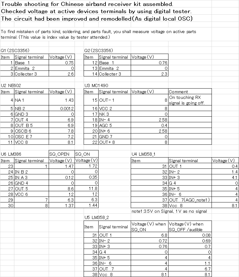
I'm now assembling Chinese airband receiver kit and remodelling it.
I just completed displaying apparatus of receiving frequency, degital generating local oscillator , adding LNA, and narrower intermideate frequency band.
Before to try to remodel narrower, I bought next kit.
This kit PCB is identified from former kit of coil type front end.
This style of front end filter is no good for filtering ability. I had serch for improvement of band pass filter.
After searching related information on internet, I found below posting.
DIY Kit for Aircraft Band Monitoring | The SWLing Post
Unfortunately I could not find filter improvement information yet.
rover.ebay.com
 Airband receiver aluminum case