After FM62429 variable attenuator the audio signal is going to LM386 amp. The same signal is going to the MC3661 filter amp and detector.
MC3361 is naturally the FM receiver IC and this receiver is using filter amp for detected signal AMP to open the channel when the signal detects.
I'm somehow wondering about the squelch performance. I shall check it on the real machine later.
BTW the analog LO airband receiver is combined with carrier squelch using AGC voltage. And this receiver does not have AGC on the front end LNA. TA7640 may share AGC performance by itself.
I bought this kit lately and I will check the above issues after assembling. So the next report shall be the introduction of my assembling.
c. 1st IF AMP, 2nd mixer, 2nd IF AMP, and detecter
MC3661 is working as the 1st IF AMP and also the 2nd mixer combined with 10.245MHz crystal oscillator. The output of MC3661 is fed into LT455 ceramic filter prior to TA7640. TA7640 is working for the 2nd IF AMP and the detecter. The output signal from the detecter is going into FM62429 variable attenuator as an audio signal and a noise source. When the received signal not being incoming, a noize is generated by the detector.
There is also receiving indicator LED signal on TA7460. This works when more than -90dBm signal being.
I much roughly estimated the sensitivity of this. Please refer to the detailed value in the attached diagram. The estimated sensitivity is -7dBμ=-114dBm open. It's comparable with IC-R6 of -4dBμ. On the manual the receiving indicator shall be lit at -90dBm=17dBμ.
Block diagram for sencitivity estimating
TA7640 characteristics curve
c. 第一、第二中間周波数AMP、第二ミキサー、検波 第一中間周波数増幅と第二ミキサーにはMC3661が用いられています。MC3661はもともとFM受信機用なので、使われている機能は一部です。ミキサーには10.7MHz→455KHz変換用局発の10.245MHz水晶発振器も内蔵されています。ミキサーからの出力455KHz信号はセラフィル経由で第二中間周波数増幅と検波回路を有するTA7640に入力されます。
The 1st local oscillator is MS5351 PLL managed by PIC18F1320. There is a rotary encoder to tune the frequency. We can select 100kHz or 10kHz step frequency by pushing the RE knob. The frequency is displayed on the front 7 segments 4 columns LEDs as 1215 at the case of 100kHz selected. At the case of 10kHz, 1 is omitted and displays as [215.0]MHz.
They say that 1215 displaying means 1215*100kHz=121.5MHz at 100kHz mode and 215.0 means 1215.0*100kHz=121.5MHz at 10kHz mode.
I shall later refer to how to operate the setting for frequency, volume, squelch level, and 25MHz adjusting.
MS5351 is based on a 25MHz crystal oscillator and can be adjusted by RE to compensate for the error. Below is PLL-BOB. There may be a low pass filter for clock output.
PLL PCB
------Appended @ 2021.12.14 ----------
I bought the kit and investigated the circuit to draw the diagram as below.
The circuit diagram of R80 PLL BOB.
--------------------------------------------
The mixer is NE602. The output signal of NE602 is going into a ceramic filter of FM radio use.
a. The front end filter and LNA The front stage filter is a stager style with two LC resonating circuits. L is D5x5 size, 4.5 turn(Estimated inductance is 68nH by WEB service "http://gate.ruru.ne.jp/rfdn/Tools/ScoilForm.asp#p1"). And C is 15pF. Between LC circuits there is 2.7pF connecting capacitor. I had simulated filter design by using ELSIE. "http://tonnesoftware.com/elsie.html" To keep the bandwidth for the airband we shall tune the front filter coil size. 60/68nH is somehow well for bandwidth and accordingly pass-through gain is declined. We should use the VNA or the spectrum analyzer to tune more precisely.
Simulation at ELSIE
LNA is NE5204 which is DC-200MHz wide and 20dB gain.
I'm wondering to buy R80 kit or not. I have been interested in various functions on R80.
1. They are saying that the LO is PLL. And I had come to know that the chip was MS5351 as was Si5351a clone. If so, their providing frequency setting function is a little bit poor. The major style of receiver usage is waiting for a signal on several determined frequencies.
2. Airband communication frequency plan is 25kHz separation and near London and New York that is 8.33kHz especially. The step frequency of R80 is 100kHz or 10kHz.
Prior to buying R80, I studied its circuit. And I will introduce it below.
I sent a request mail for Mr.ken to report what chip is used as PLL LO. He had opened the case and investigate the name on the IC chip and he taught me the name being MS5351. Alibaba is selling MS5351 as a compatible od Si5351a for amateur radio usage.
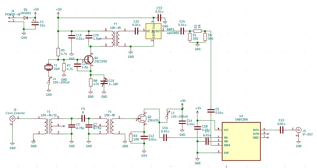
As I bought Si4732 receiver kit, I made up a crystal converter to receive air band communication. I utilized the MPU 20MHz crystal for the 5th overtone oscillating as 100MHz. The correct frequency is 100.06MHz. I composed the stagger coupled 2 10K-8t coils as a front-end filter and used 2SK439 FET for LNA.
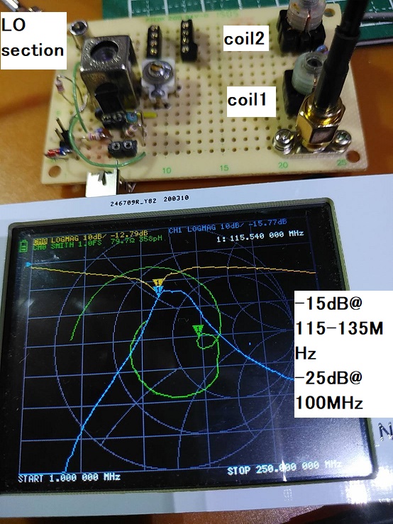
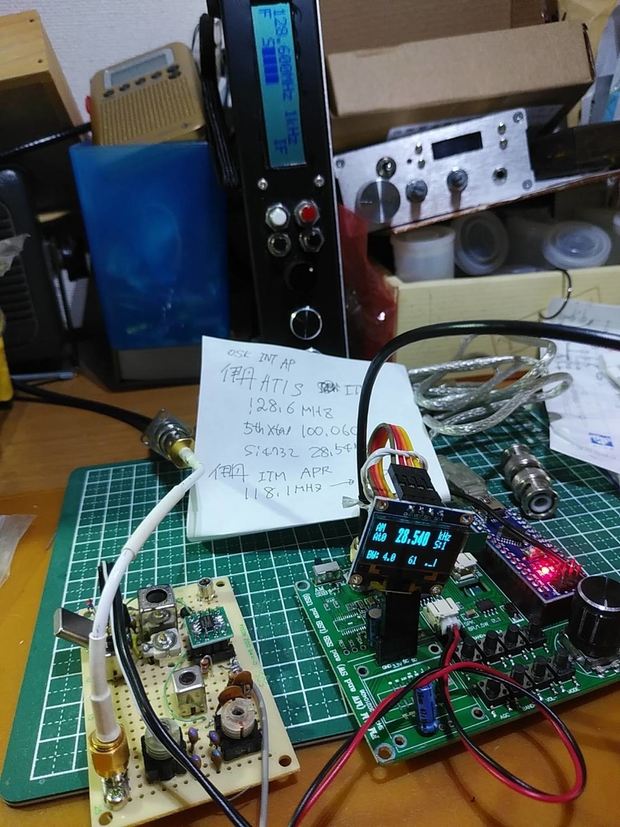
To connect the crystal converter for the Si4732 receiver I tuned Osaka international airport ATIS. As Osaka international airport ATIS's frequency is 128.6MHz, I should tune 28.54MHz derived 128.6 - 100.06 = 28.54MHz. The result of filter is -15dB between 115 - 135MHz and -25dB @ 100MHz.
The sensitivity is less than the Chinese receiver kit. I can receive a 118.1MHz signal from airplanes because of being very strong. Speaking of received sound feeling, it is special for SDR. SDR is naturally tuning modulated signal and it takes some time to generate sound after capturing modulated signal. No signal: very noisy, On capturing signal being calm at first, after then coming up demodulated sound.
To boost the signal I connected 0.1-2000MHz Wideband AMP bought from Amazone, and it brought well result. As a result, the sensitivity became as same as the Chinese airband receiver kit.
The project of the 5th overtone crystal converter brought enough achievement.