中国製航空無線キットの組立と改良を手がけました。大きな項目は局発デジタル化とスケルチ切り替えMUTEフィーリング改善が注目点と思います。
I'm thinking that the intensive points of Chinese receiver kit improvement are digitalized LO and better squelch muting feeling.
今回はそのスケルチフィーリングに関し、LTspiceで確かめみます。
This time I will check to mute feeling by using LTspice simulation.
元ネタ The original article is below.
How to improve squelch feeling for Chinese airband receiver kit 中国製エアバンドレシーバーキットのスケルチフィーリング改善
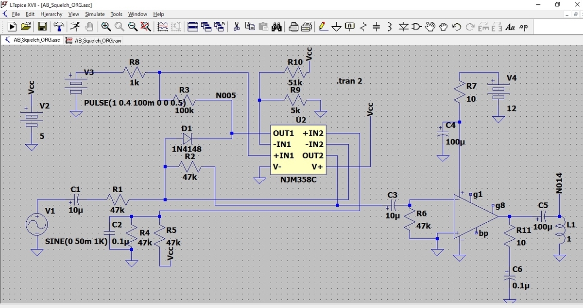
スケルチのLM386のMUTE切り替え部分に着目し、LTspiceに回路入力します。LM358のAGC増幅回路、AF増幅回路、LM386のAMP部にしぼって 入力します。
To simulate the squelch circuit partially, I gathered LM386 and LM358 spice models for the audio and power AMP portion.
まず初めの課題はLM358とLM386のモデルです。いくつかやって、asyとsubがうまくリンクしないとかの苦労しました。試行錯誤の結果をまとめると次になります。(Auto Generatedを使う)
After trying & error, I acknowledged using "AutoGenerated" for .asc.
1. LM358についてはJRCのデータを参照しました。 I referred JRC information for LM358.
2. WEBからlibのzipをD/L解凍し、・\LTspiceXVII\lib/sub/の下に入れる。
3. LTspice処理で[Files]->[open]でlib探し、開く。
4. .subchet行を探し、該当行で右クリック[create symbol]でasyを作る。
5. 作成されたシンボルは[component]指定したときに[Auto Generated]に入っている。
6. LM386についてはelectro-tech-online.comのやりとりから引用。
asyとsubを取り出し利用。
次に回路図入力での留意点です。
1.LM358の供給電源で+5Vを定義。LM386には+12V電源を用意。
2.受信音声信号にあたるものとしてLM358入力に1kHz50mVを用意。
信号電源として SINE(0 50m 1k) を定義。
3.スケルチボリウムをR値で適宜設定(閾値を0.5Vぐらいにした)
Vcc=5Vを51k、5kで分圧
4.信号検波電圧(AGC電圧)をパルス電圧源で定義。
PULSE(1 0.4 100m 0 0 0.5)
There are some issues to edit the circuit diagrams.
1. I determined the power supplies for LM358 of 5V, and for LM386 of 12V.
2. I'm using AC signal of 1kHz50mV as receiving audio sound.
3. Squelch volume setting will be 0.5V by the resister's deviation.
4. I determined AGC voltage by the pulse signal source.
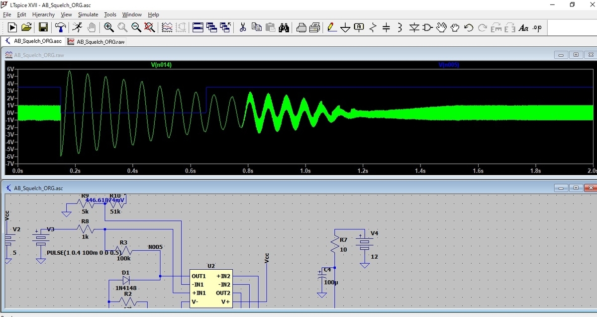
以上の設定でシミュレーションかけました。
そうすると、キットオリジナル回路ではmute時にすごいノイズ(数ヘルツで数秒間)が出ています。青トレースがAGC電圧、緑がスピーカー出力。
As the result of the simulation, there is a very large and low-frequency noise after the squelch turns on. The blue trace is AGC voltage, and the green trace is SP output.
そうこうしていると古いスケルチ問題に触れているブログ書き込みにZ_MIKLOAさんと言う方からJRCのデータシートにはMUTEのやり方解説があると教えてもらいました。
新たな情報を得たので、JRCのデータシートを読んで試してみることにします。
Same time I got a comment on the old blog article from Z_MIKLOA san about JRC datasheets. He told me that there are several methods for squelching on LM386.
Depending on this information I shall study more for LM386 squelch technic.
--この項続く--Continue--
Please check the video as before and after remodle for LM386 mute.