a. The front end filter and LNA The front stage filter is a stager style with two LC resonating circuits. L is D5x5 size, 4.5 turn(Estimated inductance is 68nH by WEB service "http://gate.ruru.ne.jp/rfdn/Tools/ScoilForm.asp#p1"). And C is 15pF. Between LC circuits there is 2.7pF connecting capacitor. I had simulated filter design by using ELSIE. "http://tonnesoftware.com/elsie.html" To keep the bandwidth for the airband we shall tune the front filter coil size. 60/68nH is somehow well for bandwidth and accordingly pass-through gain is declined. We should use the VNA or the spectrum analyzer to tune more precisely.
Simulation at ELSIE
LNA is NE5204 which is DC-200MHz wide and 20dB gain.
I'm wondering to buy R80 kit or not. I have been interested in various functions on R80.
1. They are saying that the LO is PLL. And I had come to know that the chip was MS5351 as was Si5351a clone. If so, their providing frequency setting function is a little bit poor. The major style of receiver usage is waiting for a signal on several determined frequencies.
2. Airband communication frequency plan is 25kHz separation and near London and New York that is 8.33kHz especially. The step frequency of R80 is 100kHz or 10kHz.
Prior to buying R80, I studied its circuit. And I will introduce it below.
I sent a request mail for Mr.ken to report what chip is used as PLL LO. He had opened the case and investigate the name on the IC chip and he taught me the name being MS5351. Alibaba is selling MS5351 as a compatible od Si5351a for amateur radio usage.
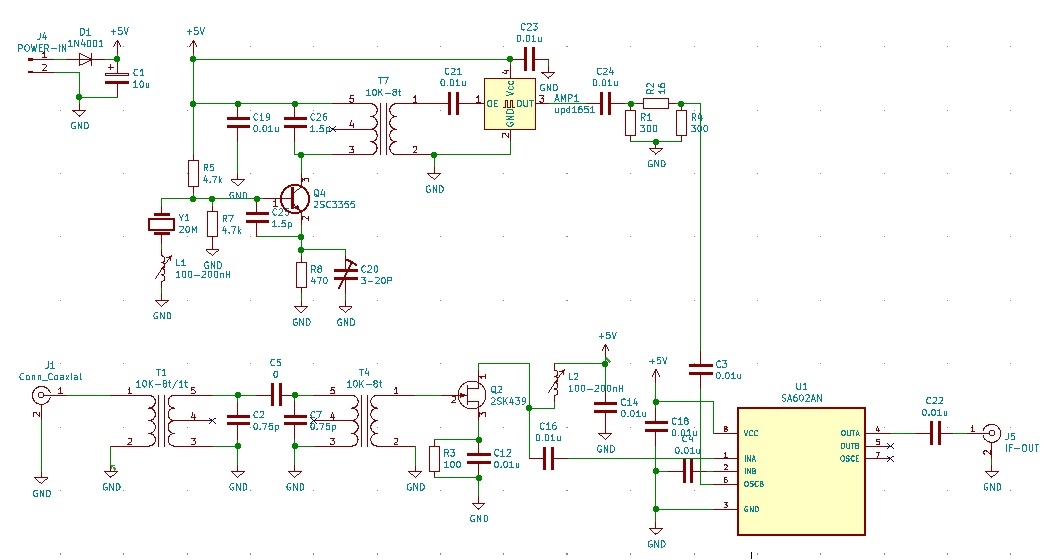
As I bought Si4732 receiver kit, I made up a crystal converter to receive air band communication. I utilized the MPU 20MHz crystal for the 5th overtone oscillating as 100MHz. The correct frequency is 100.06MHz. I composed the stagger coupled 2 10K-8t coils as a front-end filter and used 2SK439 FET for LNA.
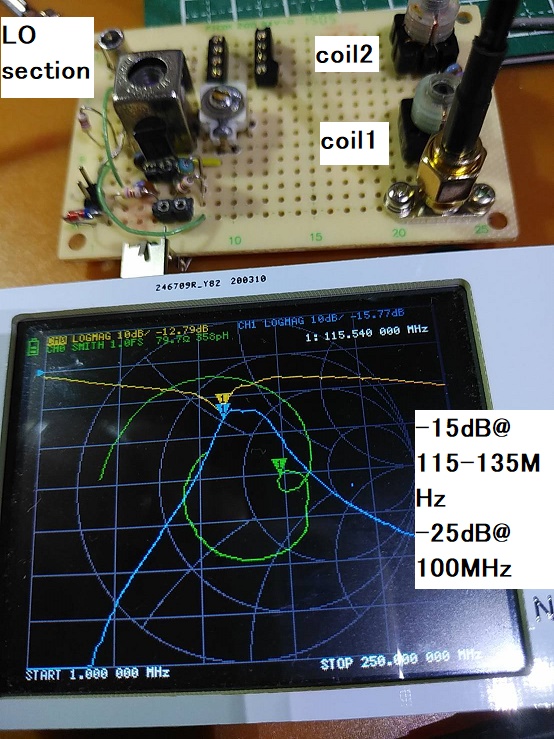
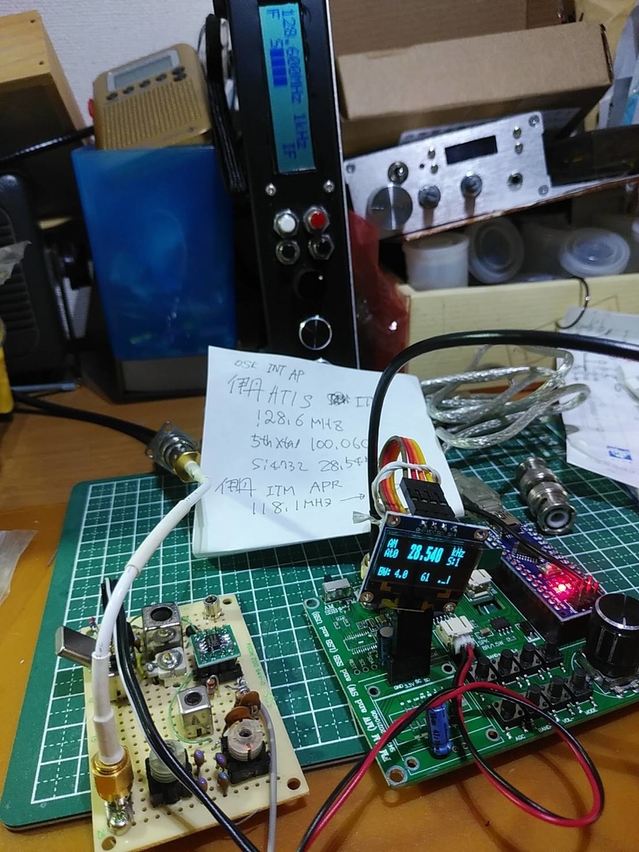
To connect the crystal converter for the Si4732 receiver I tuned Osaka international airport ATIS. As Osaka international airport ATIS's frequency is 128.6MHz, I should tune 28.54MHz derived 128.6 - 100.06 = 28.54MHz. The result of filter is -15dB between 115 - 135MHz and -25dB @ 100MHz.
The sensitivity is less than the Chinese receiver kit. I can receive a 118.1MHz signal from airplanes because of being very strong. Speaking of received sound feeling, it is special for SDR. SDR is naturally tuning modulated signal and it takes some time to generate sound after capturing modulated signal. No signal: very noisy, On capturing signal being calm at first, after then coming up demodulated sound.
To boost the signal I connected 0.1-2000MHz Wideband AMP bought from Amazone, and it brought well result. As a result, the sensitivity became as same as the Chinese airband receiver kit.
The project of the 5th overtone crystal converter brought enough achievement.
Worse sensitive. 1stis machine is composed of an enamel wire coil filter but 2nd machine is composed of PCB pattern coil one. I added the resistor for impedance matching so this causes much loss.
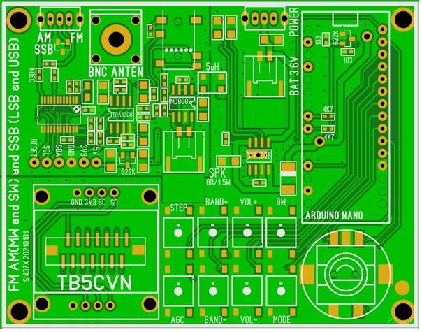
I bought the Si4732 receiver kit and assembled it. This is the same as ATS-20 with the case. The original PCB is based on Turkish HAM, TB5CVN copied and is selling it on PCB WAYs as USD5.
Connecting Si4732 receiver with airband receiver IF
There is 10.7MHz IF output on the Chinese remodeled receiver. Si4732 is set 10.7MHz AM and fed the above signal. I could hear airband radio communication on this combination. It is special as DSP receiving feeling. When signal comes, once calm and after then the demodulated sound is coming up.
For the sake of sketch improvement I had changed Arduino nano to be connected on PCB. So female header on PCB and soldered male header on Arduino nano. So I removed nano from PCB. Then I found that they had soldered Vcc, GND, and internal Vcc supply node of USB-Di cathode of nano board. To prevent USB +5V supply they remove the diode and they connected +3.3 line to Di cathode node by tricky style.
I would not use a battery and I shall supply Vcc from USB to nano. So I soldered 1S1588 of a silicon diode. It reduces 0.8V and supplies voltage results 4.2V This works well.
I had soldered and turned on. Then the circuit is unstable still. There occurred stacked along with i2c interfacing. I checked the circuit diagram and I could not find AL capacitors on a power line. I observed DC line by oscilloscope and found some hundred mv of ripple on it. I added 47uF AL capacitors on the line.
I had consumed much time to resolve this setting. 1S1588(same as 1N4001) is working well. Arrived Arduino sketch was 1.1.5 as a very old version. I shall instead it to current versio as V3.x.x.
PU2CLR Mr.Recardo is a very generous person to admit Chinese clone suppliers being using his library without any notice. He is providing version-up information for Chinese kit purchasers. I will introduce it with a Japanese translation.